Overview
This example demonstrates writing to a 20x4 character LCD module based on the HD44780 display controller using the 4-bit parallel interface mode. The example uses a blocking delay to set the update speed of an 8-bit up-counter which is displayed in decimal, hexadecimal, and binary formats on the LCD. This example can be used to explore display characteristics such as refresh rate.
Required Hardware
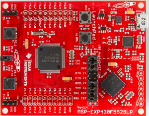
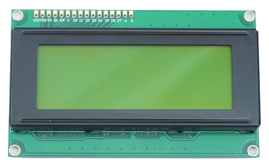
This example requires the MSP430F5529LP development board and a 20x4 character LCD display based on the Hitachi HD44780 LCD Display controller. In order to use the 4-bit parallel interface, it is best to purchase a bare display, such as the Cofufu 20x4 Black on Green LCD module from Amazon. This particular display comes with male and female headers and a 10k potentiometer to implement the contrast adjustment. This will require soldering to connect the headers to the display, and to create the display cable.
Required Connections
The example code provided requires the following connections to be made. For more information on how to make these connections, see the section for building the display cable.
| LCD Pins | Pin Description | MSP430 GPIO Pin | MSP430 Port Pin | |
|---|---|---|---|---|
| RS | LCD Register Select | 57 | P7.4 | |
| RW | LCD Read/Write Select | 35 | P2.6 | |
| EN | LCD Read/Write Strobe | 16 | P8.1 | |
| D4 | LCD Data Bus (bit 4) | 44 | P3.7 | |
| D5 | LCD Data Bus (bit 5) | 17 | P8.2 | |
| D6 | LCD Data Bus (bit 6) | 27 | P1.6 | |
| D7 | LCD Data Bus (bit 7) | 36 | P2.7 |
| VSS | LCD Controller ground | This must be connected to one of the GND pins on the development board. |
|
| VDD | LCD Controller power | This must be connected to one of the 5V pins on the development board. |
|
| V0 | LCD contrast adjust voltage | This must be connected to an adjustable voltage between ground and at least 3.3V. |
|
| A | LCD backlight Anode (power) | This must be connected to one of the power pins (5V or 3V3) on the development board. |
|
| K | LCD backlight Kathode (ground) | This must be connected to one of the GND pins on the development board. |
NOTE: In the 4-bit parallel mode, pins D0, D1, D2, D3 do not need to be connected.
Required Libraries
In order to build the example project, follow the instructions here for how to create and configure a new project. This example requires the following operating environment files:
- MSP430F5529LP.h
- MSP430F5529LP.gel
- MSP430F5529LP_CLOCK.h
- MSP430F5529LP_CLOCK.c
- MSP430F5529LP_GPIO.h
- MSP430F5529LP_GPIO.c
- MSP430F5529LP_TIMERA2.h
- MSP430F5529LP_TIMERA2.c
- LCD_HD44780_4BIT.h
- LCD_HD44780_4BIT.c
Example Code
The example code is provided as a main.c file that is available on GitHub at (LCD_Display_4Bit_Counting_Example), or if preferred, it can be cut-pasted from the window below.
/* ########################################################################## */ /* * This file was created by www.DavesMotleyProjects.com * * This software is provided under the following conditions: * Permission is hereby granted, free of charge, to any person obtaining * a copy of this software and associated documentation files (the * 'Software'), to deal in the Software without restriction, including * without limitation the rights to use, copy, modify, merge, publish, * distribute, sublicense, and/or sell copies of the Software, and to * permit persons to whom the Software is furnished to do so, subject to * the following conditions: * * THE SOFTWARE IS PROVIDED 'AS IS', WITHOUT WARRANTY OF ANY KIND, * EXPRESS OR IMPLIED, INCLUDING BUT NOT LIMITED TO THE WARRANTIES OF * MERCHANTABILITY, FITNESS FOR A PARTICULAR PURPOSE AND NONINFRINGEMENT. * IN NO EVENT SHALL THE AUTHORS OR COPYRIGHT HOLDERS BE LIABLE FOR ANY * CLAIM, DAMAGES OR OTHER LIABILITY, WHETHER IN AN ACTION OF CONTRACT, * TORT OR OTHERWISE, ARISING FROM, OUT OF OR IN CONNECTION WITH THE * SOFTWARE OR THE USE OR OTHER DEALINGS IN THE SOFTWARE. * */ /* ########################################################################## */ /* ===========================================================================*/ /* * This program writes to a 20x4 LCD display based on the HD44780 display * controller using the 4-bit parallel addressing mode. The example uses an * interval timer to display an up-counter in decimal, hexadecimal and binary * formats. This example can also be used to explore the refresh rates of the * LCD. To fast, and the display becomes unreadable. A note of caution, the * refresh rate of the LCD is highly dependent on temperature. * * Version 1.0 * * Rev. 1.0, Initial Release * * */ /* ===========================================================================*/ #include "MSP430F5529LP.h" #include "MSP430F5529LP_CLOCK.h" #include "MSP430F5529LP_TIMERA2.h" #include "MSP430F5529LP_GPIO.h" #include "LCD_HD44780_4BIT.h" /****************************************************************************** PUBLIC DEFINITIONS ******************************************************************************/ /****************************************************************************** PUBLIC VARIABLES ******************************************************************************/ /****************************************************************************** PRIVATE DEFINITIONS (static const) ******************************************************************************/ #define BYTETOBINARYPATTERN "%d%d%d%d%d%d%d%d" #define BYTETOBINARY(byte) \ (byte & 0x80 ? 1 : 0), \ (byte & 0x40 ? 1 : 0), \ (byte & 0x20 ? 1 : 0), \ (byte & 0x10 ? 1 : 0), \ (byte & 0x08 ? 1 : 0), \ (byte & 0x04 ? 1 : 0), \ (byte & 0x02 ? 1 : 0), \ (byte & 0x01 ? 1 : 0) /****************************************************************************** PRIVATE FUNCTION PROTOTYPES (static) ******************************************************************************/ static void initialize(void); static void Update_LCD_Display(void); /****************************************************************************** PRIVATE VARIABLES (static) ******************************************************************************/ static uint8_t s_count_u8; /****************************************************************************** Subroutine: main Description: program entry point at startup. Inputs: None Outputs: 0 ******************************************************************************/ int main( void ) { // perform initialization initialize(); for (;;) // Loop forever... { delay(250); // perform a blocking delay of 250 ms s_count_u8++; // increment the counter Update_LCD_Display(); // Update the LCD display } return 0; } /****************************************************************************** Subroutine: initialize Description: Performs the initalization of the main program. This also initializes the MSP430F5529LP operating environment. Inputs: None Outputs: None ******************************************************************************/ void initialize(void) { // ################################################################### // Add operating environment initialization here MSP430F5529LP_CLOCK_Initialize(); MSP430F5529LP_TIMERA2_Initialize(); MSP430F5529LP_GPIO_Initialize(); /* Initialize the 20x4 LCD display * LcdPin_RS = 57; // P7.4 * LcdPin_RW = 35; // P2.6 * LcdPin_EN = 16; // P8.1 * LcdPin_D4 = 44; // P3.7 * LcdPin_D5 = 17; // P8.2 * LcdPin_D6 = 27; // P1.6 * LcdPin_D7 = 36; // P2.7 */ LCD_Initialize(57, 35, 16, 44, 17, 27, 36); // ################################################################### // Add program specific initialization here // Enable the Debug LEDs P1DIR_bits.P1DIR0 = 1; // Set P1.0 (LED1) to an Output P4DIR_bits.P4DIR7 = 1; // Set P4.7 (LED2) to an Output P1OUT_bits.P1OUT0 = 1; // Set P1.0 initial value P4OUT_bits.P4OUT7 = 1; // Set P4.7 initial value s_count_u8 = 0u; Update_LCD_Display(); // ################################################################### // Last step before exiting, enable global interrupts __enable_interrupt(); } /****************************************************************************** Subroutine: Update_LCD_Display Description: This function updates the LCD display values. Inputs: None Outputs: None ******************************************************************************/ static void Update_LCD_Display(void) { /* In addition to updating the LCD, set and clear the P1.0 LED during LCD * processing. This gives an indication of how long it takes to update * the LCD display. It is important to keep in mind that the LCD will * "block" during update, and this can affect application performance. * Interrupts are not disabled during LCD updates, but the application's * ability to keep up with processing between interrupts could be. Note * that the P1.0 LED signal is also available at jumper JP8. */ P1OUT_bits.P1OUT0 = 1; LCD_SetPosition(LCD_ROW1); LCD_Print("LCD (4bit) Example "); LCD_SetPosition(LCD_ROW2); LCD_Print("Decimal: %3d", s_count_u8); LCD_SetPosition(LCD_ROW3); LCD_Print("Hexadecimal: %3X", s_count_u8); LCD_SetPosition(LCD_ROW4); LCD_Print("Binary: "BYTETOBINARYPATTERN, BYTETOBINARY(s_count_u8)); P1OUT_bits.P1OUT0 = 0; } /****************************************************************************** End of File: main.c ******************************************************************************/ |
Initialization
In the example code, there are 3 main sections to the initialization.
- The first section is the initialization of the operating environment files,
- the second section includes application specific initialization, and
- the third section enables the global interrupts.
It is recommended that all projects using the operating environment follow this convention.
void initialize(void)
{
    // ###################################################################
    // Add operating environment initialization here

    MSP430F5529LP_CLOCK_Initialize();
    MSP430F5529LP_TIMERA2_Initialize();
    MSP430F5529LP_GPIO_Initialize();

    /* Initialize the 20x4 LCD display
     * LcdPin_RS =  57;  // P7.4
     * LcdPin_RW =  35;  // P2.6
     * LcdPin_EN =  16;  // P8.1
     * LcdPin_D4 =  44;  // P3.7
     * LcdPin_D5 =  17;  // P8.2
     * LcdPin_D6 =  27;  // P1.6
     * LcdPin_D7 =  36;  // P2.7
     */
    LCD_Initialize(57, 35, 16, 44, 17, 27, 36);


    // ###################################################################
    // Add program specific initialization here

    // Enable the Debug LEDs
    P1DIR_bits.P1DIR0 = 1;         // Set P1.0 (LED1) to an Output
    P4DIR_bits.P4DIR7 = 1;         // Set P4.7 (LED2) to an Output
    P1OUT_bits.P1OUT0 = 1;         // Set P1.0 initial value
    P4OUT_bits.P4OUT7 = 1;         // Set P4.7 initial value

    s_count_u8 = 0u;


    // ###################################################################
    // Last step before exiting, enable global interrupts

    __enable_interrupt();
}
Section 1 - initialization of the operating environment
Since the CLOCK, TIMERA2, and GPIO library modules are included in this example, the initialization for these modules is performed in section one. The standard convention for the operating environment is that every library module includes an initialization function, and that function must be called before the module or its functions are used. The order of initialization is not important, except for the following rules:
- 1) CLOCK initialization is always required, and must always be initialized first.
- 2) hardware library modules must be initialized before accessory library modules.
- ...and as with most rules there is always one exception.
- 3) The BUTTON library module is a hybrid of hardware and accessory. If used, it must be initialized as the last hardware module.
After the hardware initialization, the LCD library is initialized, which includes passing it the GPIO pin numbers for RS, RW, EN, D4, D5, D6, and D7. Although the example code was written to use these connections, the code can be modified to use other connections. In that case, the initialization would also need to be modified to identify the GPIO pins used.
Section 2 - application specific initialization
The application specific initialization for this example enables the two LEDs on the development board by setting their direction and initial state. It also initializes the variable that will store the value of the 8-bit up-counter value.
Section 3 - enable global interrupts
The last section enables the global interrupts. This is normally done as the last step during initialization, unless there is a specific need to do it otherwise. The initialization of any interrupt driven library files will have enabled the interrupts for those modules, but they will not run until the global interrupts are enabled using __enable_interrupt();.
The Main Loop
The main function consists of a simple "forever loop" that performs a blocking delay of 250 ms, increments the up-counter, and updates the LCD display. This is a very simple program, but it can be useful to investigate the LCD display behavior (such as refresh rate, or "ghosting"), and the behavior of the LCD display library (such as execution time to write a character).
int main( void )
{
    // perform initialization
    initialize();

    /* Update the LCD display for the first time. This is done after
     * initialization because the LCD library uses TimerA2 delay functions,
     * and global interrupts must be enabled for them to work properly.
     */
    Update_LCD_Display();

    for (;;)    // Loop forever...
    {
        delay(250);             // perform a blocking delay of 250 ms
        s_count_u8++;           // increment the counter
        Update_LCD_Display();   // Update the LCD display
    }

    return 0;
}
IMPORTANT: It is important to note is that there is an extra initialization step that is performed after the standard initialization function and before entering the forever loop. Updating the LCD display as part of initialization ensures that the display provides a known value to the user on start-up. This ensures that the display does not continue to display old data (or uninitialized data) to the user until the first time it is updated. Without this the display would not be updated until after the first 250 ms delay.
The reason that updating the LCD is done after initialization is that the LCD library uses the TIMERA2 module delay functions and global interrupts must be enabled for them to work properly. As with most things in software programming, there are several ways to do everything. An alternative for this specific example could be to re-arrange the order of operations in the forever loop to update the LCD display first, however I would strongly discourage this approach. This results in the desired behavior, however it makes it less obvious that the intention is to initialize the LCD immediately upon start-up.
If software programming is one of your ambitions, this is an important lesson: always write your code so that it will be obvious to the next person, what it does, and why it does it. Approximately 50% of software errors that result in product recalls are made during software changes after a product is released. Many times this is because some aspect of the code was not obvious to the person making the change.
A better alternative approach would be to add a 4th section to the standard initialization called "program specific initialization that requires interrupts", and move updating the LCD for the first time back into the initialization function. This would make it obvious that updating the LCD is intended to be part of initialization, and that interrupts are required for it to work properly.
Updating The LCD Display Function
The Update_LCD_Display function writes the text to be displayed to the LCD. In this example, the cursor position is set to the beginning of each row, and the text for the entire row is written to the display. Note that even for the first row spaces are included in the quotes after the word "Example" to fill in the rest of the row. This provides a robust solution that re-writes the entire row every time. That way if old data exist, or if noise or a poor connection causes erroneous characters to appear, they are corrected the next time the display updates.
static void Update_LCD_Display(void)
{
    /* In addition to updating the LCD, set and clear the P1.0 LED during LCD
     * processing. This gives an indication of how long it takes to update
     * the LCD display. It is important to keep in mind that the LCD will
     * "block" during update, and this can affect application performance.
     * Interrupts are not disabled during LCD updates, but the application's
     * ability to keep up with processing between interrupts could be. Note
     * that the P1.0 LED signal is also available at jumper JP8.
     */

    P1OUT_bits.P1OUT0 = 1;

    LCD_SetPosition(LCD_ROW1);
    LCD_Print("LCD (4bit) Example  ");
    LCD_SetPosition(LCD_ROW2);
    LCD_Print("Decimal:         %3d", s_count_u8);
    LCD_SetPosition(LCD_ROW3);
    LCD_Print("Hexadecimal:     %3X", s_count_u8);
    LCD_SetPosition(LCD_ROW4);
    LCD_Print("Binary:     "BYTETOBINARYPATTERN, BYTETOBINARY(s_count_u8));

    P1OUT_bits.P1OUT0 = 0;
}
The LCD_Print function works just like the C library function printf. The format string contains embedded format tags, like %3d and %3X, which are replaced by the value specified in s_count_u8 using the formatting specified. %3d reserves 3 spaces to display a decimal number, and %3X reserves 3 spaces to display capitalized hexadecimal values.
The C library doesn't have functions to display binary values, so the macros BYTETOBINARYPATTERN, and BYTETOBINARY() are used to create the binary format and values. BYTETOBINARYPATTERN is replaced by the format specifier "%d%d%d%d%d%d%d%d", which says to place 8 decimal values one right after the other with no spaces in between. The macro BYTETOBINARY() is passed the count value s_count_u8, and creates a list of 8 comma separated short-hand IF/THEN statements like (byte & 0x80 ? 1 : 0) that says if the eighth bit is non-zero return a 1, else return a 0. For a count value of s_count_u8 = 53 decimal, the string of IF/THEN statements would evaluate to be the string of values: 0,0,1,1,0,1,0,1.
    #define BYTETOBINARYPATTERN    "%d%d%d%d%d%d%d%d"

    #define BYTETOBINARY(byte) \
      (byte & 0x80 ? 1 : 0), \
      (byte & 0x40 ? 1 : 0), \
      (byte & 0x20 ? 1 : 0), \
      (byte & 0x10 ? 1 : 0), \
      (byte & 0x08 ? 1 : 0), \
      (byte & 0x04 ? 1 : 0), \
      (byte & 0x02 ? 1 : 0), \
      (byte & 0x01 ? 1 : 0)
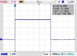
One other thing being done within this LCD Update function is the setting and clearing of the P1.0 LED using the statements P1OUT_bits.P1OUT0 = X, where X = 0 or 1. By asserting the LED during display processing it is possible to use an oscilloscope to measure how long it takes to update the LCD display.
In the example code, the entire display is being updated each time, even though large sections of text like "Decimal:", and "Hexadecimal:" don't change. This was done intentionally to capture "worst-case" processing times, and to make the example robust so that it recovers if there are connection issues. Processing time can be reduced a little by only updating the values that are changing, but it does reduce the robustness of the design to interference.
In the example, there are 84 commands being sent ot the display for each LCD update: 4 set position commands, and 80 write character commands. The measured time for the entire update process was 11.8 ms, which results in per command processing time of 0.14 ms/command.
The End Result
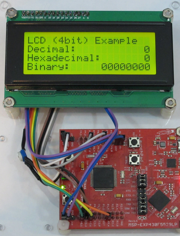
Once the example code is built and executed, the end result should be an up-counter that is displayed in decimal, hexadecimal and binary formats, as shown below. (The video snippet only counts from 15 to 28 decimal, but the actual example will count from 0 through 255)
|
Now that the example code is up an running, consider changing a few things an see what happens. For example:
- Change the blocking delay value to something very small like delay(1). This will make the display update as fast as possible. Are the digits even readable at this speed?
- Change the up-counter to count by 2's (like s_count_u8 += 2;). What happens to the lowest bit of the binary counter? Try counting by 4, or 8, or other multiple of 2^N.
- Change the format specifier for hexadecimal from %3X" to %3x". What happens to how the hex values are displayed? Try %03X". What does that do?
Building the Display Cable
Before running the example code, the LCD display needs to be connected to the development board. To do this I started with a 20 cm (approx. 8 inch) Female to Female jumper wire ribbon cable and several pieces of 2.5 mm x 30 mm pre-cut heat shrink tubing. I selected 8 different colors to connect to the 4 control and data lines, and then selected 2 sets of the same 2 color combinations to connect to pwr/gnd for the LCD controller and pwr/gnd for the LCD backlight. When the cable was completed it looked like the image below.
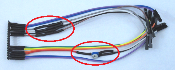
There are two modifications to the cable (marked by red circles below) that require some explanation. The addition of series resistors in the D4-D7 data lines, and the connection of the contrast adjust potentiometer.
The HD44780 LCD Display Controller has a minimum high level input voltage of 2.2V, so all signals output from the MSP430 will be acceptable to the LCD, however when the MSP430 reads from the LCD, the signals on D4-D7 will be driven to 5V, and that is not acceptable, as the MSP430 is not 5V tolerant! Based on measurements that I made on one of my displays, it appears that the HD44780 is limited to driving approx. 1 mA max, which is below the absolute maximum current allowed into the MSP430 protection diodes of 2 mA. This means that if the D4-D7 data lines were connected directly to the MSP430 it would probably be fine. However, it is never a good idea to rely on undocumented features. I added 1 kOhm resistors in series with the four D4-D7 connections. This ensures that the current will always be within a safe level. Any value greater than 1 kOhm would work, but I would recommend staying between 1 kOhm to 2.2 kOhm.
On the V0 signal line I added the 10 kOhm potentiometer that came with the Cofufu display. The potentiometer is a 3-pin device that is intended to be soldered to a PC board. I bent the 3 pins flat, cut the wire for the V0 signal at about 4 inches, and soldered the center-tap pin to the red V0 wire. On the other side of the potentiometer I added two 4 inch wires (white and black) with female receptacles. By connecting the two wires between ground and either the 3V3 or 5V supply, it is possible to adjust the contrast properly.
Not all displays have the pins marked. The pin ordering is as follows when viewed from the front side. It is recommended that this be confirmed using the manufacturer's datasheet, if one is available.

After soldering the female receptacle (provided with the Cofufu) to the backside of the display, I soldered the wires directly pins on the male header (also provided with the Cofufu). The end result when viewed from the backside of the display is shown below. Keep in mind that the pin names shown above, run in the opposite direction when viewed from the backside. The pin color combinations, running from left to right are: (Pin K - Purple) (Pin A - Blue) (Pin D7 - Grey) (Pin D6 - White) (Pin D5 - Black) (Pin D4 - Brown) (Pin E - Green) (Pin RW - Yellow) (Pin RS - Orange) (Pin V0 - Red) (Pin VDD - Blue) (Pin VSS - Purple).
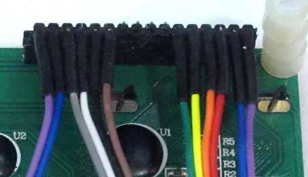
The image below shows the fully connected setup.
I connected the backlight anode (Pin A) to the 3V3 supply pin. The LCD backlight connections are intended to be connected to a +5V source (A=+5V, K=GND), however the backlight will function at +3.3V. I think this provides a less harsh and glaring look when using the Yellow/Green displays.
NOTE: Be careful when using the photo as a reference, there are two sets of white/black wires. The white and black wires for the potentiometer are the ones connected to the 5V and GND pins.