Overview
This webpage provides information about the DEFINITIONS hardware library created for the MSP430F5529LP Development Board.
Contains
- MSP430F5529LP.h
- MSP430F5529LP.gel (related, see below)
The MSP430F5529LP.h file contains the definitions for the MSP430F5529 micrcontroller registers. These definitions come from the msp430x5xx family user guide, and are translated into C-code for use in the Code Composer Studio IDE. The register addresses come from the msp430f5529 datasheet. This file must be included in all projects in order to use the code examples provided on this website.
The MSP430F5529LP.gel file is related to the MSP430F5529LP.h file. The .gel file is essentially a duplicate of the .h file, except that it only contains the #define statements. This file is the symbol map that tells the debugger how to display the peripheral registers. Although it is not technically required to run any of the example code, it is highly recommended. The .gel file must be set-up as part of creating the project, which is explained here. It cannot simply be included in the project like the .h and .c files.
How to Use The Register Definitions
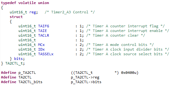
The register definitions are provided in a C union typedef that combines a register access method, and a bit-field access method using a C structure. An example definition is shown below of the Timer2 control register. Underneath the structure definition, three #defines are provided. The pointer p_TA2CTL #define maps the location of the structure within the microcontroller memory. The #define for TA2CTL provides register access, and the #define for TA2CTL_bits provides bit-field access to the structure. This methodology is used consistently throughout the file. The regname by itself always provides register access, and regname_bits always provides bit-filed access.
|
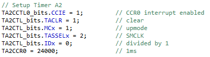
The small code snippet below of Timer A2 initialization shows examples of both access methods.
|
The assignment of TA2CCR0 = 24000, is a register access method. This means that the value of 24000 is written to the entire TA2CCR0 register. After the execution of the assignment the TA2CTL register would have the value '0101110111000000'. If the assignment had been TA2CCR0 = 1, the post execution value would be '0000000000000001'. The point being that after using a register access method there are no unaffected bit positions. The entire register value is changed.
For cases where a register is segmented into various control fields, the bit-field method is provided to make the assignment of a single field easier. For example, TA2CTL_bits.TASSELx = 2 writes the binary value '10' to bit positions 9 and 8 of the TA2CTL Register. After the execution of the assignment the TA2CTL register would have the value 'xxxxxx10xxxxxxxx', where x represents the unchanged bit values prior to the assignment.
There are several advantages to using the bit-field methods provided. The first advantage is that you don't need to know what bit positions the values are being written to, the compiler will take care of all of that based on the definitions in the MSP430F5529LP.h file. The most important advantage however is that it removes the potential for human error that comes with the traditional masking and shifting methods. The compiler will not allow you to select a bit-field access member that doesn't exist or that isn't appropriate for the selected register. Another advantage with modern IDEs, is that auto-complete will provide a list of the available options after you enter the period "." following regname_bits.
The one disadvantage to the bit-field access method is that the compiler will read-modify-write the entire register for each bit-field assignment. For most cases, such as initialization of a peripheral which occurs only at start-up, this is an insignificant disadvantage. For cases where re-initialization of multiple bit-fields is required to occur during run-time, in a time-critical routine, then using the register access method would be preferred using custom #defines or masking, shifting, and combining of the desired values.
How to Create Additional Register Definitions
The MSP430F5529LP.h currently only contains definitions for those peripherals that are used by the Operating Environment. This should be sufficient for most people. If however you find that you need something defined that is not currently available, there are two options. 1) Contact me and see if I will do it. After all, if you have a need for it, others eventually will too. Or, 2) Make the modifications yourself. If you choose option 2, here's a quick tutorial for how to do it.
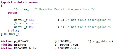
The easiest option is to copy a similar set of definitions and modify as needed. Here is an example of the general format of the definition structure for most registers.
|
Things to Consider:
- Make sure the standard type matches the size of the register (uint16_t or uint8_t) and that all of the types match for both the register and the bit-fields.
- Assign the bit-fields in the structure from Least Significant Bit (bit 0) to the Most Significant Bit (bit 7 or 15), with LSB defined first (top) in the structure, with MSB define last (bottom).
- If there are "Reserved" bit-fields, DO put them in the structure with the correct size, but DO NOT give these a name. Some people try to make up names for these like RSVD1, RSVD2, etc. The compiler doesn't need a name, and by not naming them they are by definition inaccessible, which is what you want. It is always best to write code in ways that remove the possibility of making mistakes. If the Most Significant Bits are "Reserved", you can just leave these out of the structure. The compiler doesn't need these to be defined. They will simply be inaccessible. Note that the TA2CTL structure in the example contains both kinds of Reserved fields.
- Replace "REGNAME" with the register name as it appears in the msp430x5xx family user guide. REGNAME will be in ALL CAPS. Where the user guide defines "x" in the name, such as TAxCTL, replace "x" with the appropriate value. For example, the MSP430F5529 has 3 Timer A Peripherals, And so there are 3 different control registers: TA0CTL, TA1CTL, and TA2CTL.
- The bit-field names should be exactly as they appear in the user guide (example below), which will be ALL CAPS, with one exception. In order to maintain the file convention, add a lower-case "x" post-script to names that are multi-bit fields. This is my personal convention, so it's up to you whether you use it or not, but it adds clarity to which fields contain more complexity than just On/Off.
- Replace reg_address with the correct address for the peripheral register that is being defined. To do this, find the Peripheral File Map in the msp430f5529 datasheet and navigate to the register definitions for the peripheral being defined (example below). Replace reg_address with the value of Base Address + OFFSET.
- Finally, if you are making changes to the MSP430F5529LP.h file, do not forget to also update the MSP430F5529LP.gel file! The .gel file is a duplicate of the .h file, except that it only contains the #define statements. This file is the symbol map that tells the debugger how to display your newly defined registers.
Additional Information to Support the Example Code
The following section includes some additional information from both the msp430x5xx family user guide and the msp430f5529 datasheet that help to make the instructions above more clear.
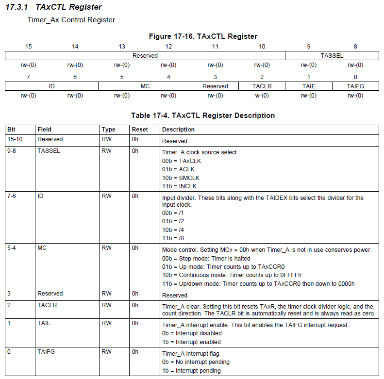
The following is the Timer_Ax Control Register definition from the user guide. Be careful, the user guide presents the bit-fields in the order of MSB to LSB. This is opposite to how they need to be defined in the C structure.
|
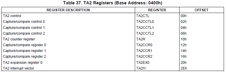
The following is the TA2 Registers table from the Peripheral File Map section of the msp430f5529 datasheet. The register address is the value of the Base Address + OFFSET. In this example, the address of TA2CTL = 0x4000, the address of TA2CCTL0 is 0x0402, the address of TA2CCTL1 is 0x0404, and so on.
|